


Crankshaft Position Sensor
What is Crankshaft Position Sensor (CPS)?
The function of the crankshaft position sensor is to determine the position of the crankshaft, that is, the rotation angle of the crankshaft and the engine speed. It usually works with the camshaft position sensor to determine the basic ignition timing. We all know that the engine starts to ignite at the end of the compression stroke, so how does the engine computer know which cylinder to ignite? It is calculated by the signals of the crankshaft position sensor and the camshaft position sensor. Through the crankshaft position sensor, you can know which cylinder piston is at the top dead center. Through the camshaft position sensor, you can know which cylinder piston is in the compression stroke. In this way, the engine computer knows when to fire which cylinder.
Tips: The Camshaft Sensor monitors the positions of the camshaft to allow for correct ignition timing. The Crankshaft Sensor detects the position of the crankshaft allowing the ECU to calculate its position in relation to the pistons in the engine.
Different Types of crankshaft position sensor
There are three main types of crankshaft sensors: magneto-electric induction, Hall effect and photoelectric.
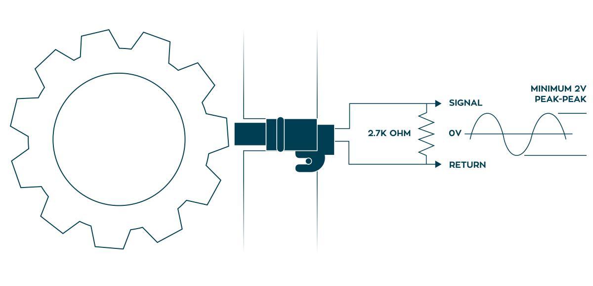
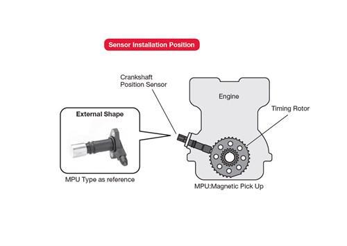
1. Magnetic induction type:
The magneto-electric induction type speed sensor and the crankshaft position sensor are installed in the distributor on the upper and lower levels. The sensor consists of a permanent magnet induction detection coil and a rotor (timing rotor and speed rotor), and the rotor rotates with the distributor shaft. The timing rotor has one, two or four teeth, and the speed rotor has 24 teeth. The permanent magnet induction detection coil is fixed on the distributor body. If the speed sensor signal and the crankshaft position sensor signal are known, as well as the working sequence of each cylinder, the crankshaft position of each cylinder can be known. The rotor signal plate of the magneto-inductive speed sensor and crankshaft position sensor can also be installed on the crankshaft or camshaft.
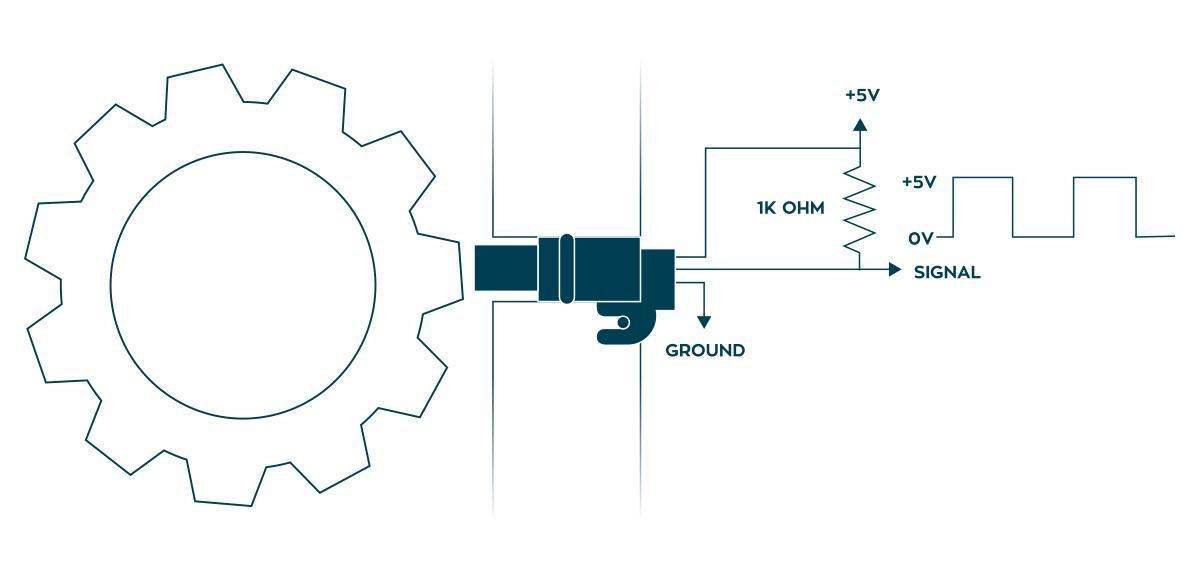
2. Hall effect:
Hall effect speed sensor and crankshaft position sensor are a signal generator that utilizes the Hall effect. The Hall signal generator is installed in the distributor, coaxial with the distributor head, and is integrally fixed on the distributor plate by the packaged Hall chip and permanent magnet. The number of notches on the trigger impeller is the same as the number of engine cylinders. When the blade on the trigger impeller enters between the permanent magnet and the Hall element, the magnetic field of the Hall trigger is bypassed by the blade. At this time, no Hall voltage is generated and the sensor has no output signal; when the gap on the trigger impeller enters the permanent magnet When it is between the Hall element and the Hall element, the lines of magnetic force enter the Hall element, the Hall voltage rises, and the sensor outputs a voltage signal.
3. Photoelectric:
The photoelectric crankshaft position sensor is generally
installed in the distributor and consists of a signal generator and a signal
plate with a light hole. The signal plate and the distributor shaft rotate
together. The outer ring of the signal plate has 360 lithography gaps, which
produce a signal with a crank angle of 1 °; a little bit inside, there are 6
light holes evenly spaced at 60 °, resulting in a crank angle of 120 °. Signal,
one of the light holes is wider, used to generate a signal relative to the top
dead center of cylinder 1. The signal generator is installed on the shell of
the distributor and consists of two light-emitting diodes, two photodiodes and
a circuit. The light-emitting diode is facing the photodiode. The signal plate
is located between the light-emitting diode and the photodiode. Because there
are light holes on the signal plate, light transmission and shading alternately
change. When the light-emitting diode beam hits the photodiode, the photodiode
generates a voltage; when the light-emitting diode beam is blocked, the
photodiode voltage is 0. After these voltage signals are partially reshaped and
amplified by the circuit, they send signals when the crankshaft angle is 1° and
120° to the electronic control unit, and the electronic control unit calculates
the engine speed and crankshaft position based on these signals.
Among
the permanent magnet motors, the permanent magnet motors using the Halbach
array structure have an air gap magnetic field that is closer to the sinusoidal
distribution than traditional permanent magnet motors. With the same amount of
permanent magnet materials, the Halbach permanent magnet motor has a greater
air gap magnetic density. The iron loss is small. In addition, Halbach ring
arrays are also widely used in permanent magnetic bearings, magnetic
refrigeration equipment and magnetic resonance equipment.