


Home / Permanent Magnet Motors
SPM vs IPM
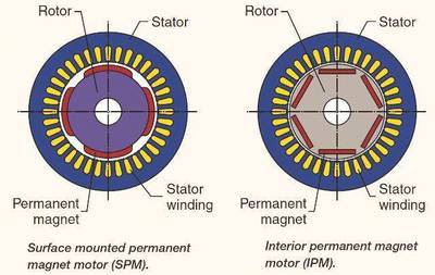
A PM motor can be separated into two main categories: surface permanent magnet motors (SPM) and interior permanent magnet motors (IPM) (see Figure 3). Neither motor design type contains rotor bars. Both types generate magnetic flux by the permanent magnets affixed to or inside of the rotor.
SPM motors have the magnets affixed to the exterior of the rotor surface. Because of this mechanical mounting, their mechanical strength is weaker than that of IPM motors. The weakened mechanical strength limits the motor's maximum safe mechanical speed. In addition, these motors exhibit very limited magnetic saliency (Ld ≈ Lq). Inductance values measured at the rotor terminals are consistent regardless of the rotor position. Because of the near unity saliency ratio, SPM motor designs rely significantly, if not completely, on the magnetic torque component to produce torque.
IPM motors have the permanent magnet imbedded into the rotor itself. Unlike their SPM counterparts, the location of the permanent magnets make IPM motors very mechanically sound, and suitable for operating at very high speeds. These motors also are defined by their relative high magnetic saliency ratio (Lq > Ld). Due to their magnetic saliency, an IPM motor has the ability to generate torque by taking advantage of both the magnetic and reluctance torque components of the motor.
PM motor structures
PM motor structures can be separated into two categories: interior and surface. Each category has its subset of categories. A surface PM motor can have its magnets on or inset into the surface of the rotor, to increase the robustness of the design. An interior permanent magnet motor positioning and design can vary widely. The IPM motor's magnets can be inset as a large block or staggered as they come closer to the core. Another method is to have them imbedded in a spoke pattern.
PM motor inductance variation with load
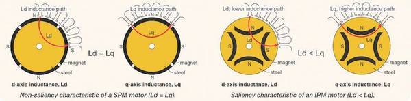
Only so much flux can be linked to a piece of iron to generate torque. Eventually, the iron will saturate and no longer allow flux to link. The result is a reduction to the inductance of the path taken by a flux field. In a PM machine, the d-axis and q-axis inductance values will reduce with increases to the load current.
The d and q axis inductances of an SPM motor are nearly identical. Because the magnet is outside of the rotor, the inductance of the q axis will drop at the same rate as the d axis inductance. However, the inductance of an IPM motor will reduce differently. Again, the d-axis inductance is naturally lower because the magnet is in the flux path and does not generate an inductive property. Therefore, there is less iron to saturate in the d axis, which results in a significantly lower reduction in flux with respect to the q axis.
Flux weakening/intensifying of PM motors
Flux in a permanent magnet motor is generated by the magnets. The flux field follows a certain path, which can be boosted or opposed. Boosting or intensifying the flux field will allow the motor to temporarily increase torque production. Opposing the flux field will negate the existing magnet field of the motor. The reduced magnet field will limit torque production, but reduce the back-emf voltage. The reduced back-emf voltage frees up voltage to push the motor to operate at higher output speeds. Both types of operation require additional motor current. The direction of the motor current across the d axis, provided by the motor controller, determines the desired effect.
Angle of excitation
The angle of excitation is the angle at which the vector sum of the d-axis and q-axis waveforms are excited to the motor with respect to the d axis. The d axis is always viewed to be where the magnet exists. Maximum magnetic flux is achieved at the q axis, which is 90 electrical deg from the d axis. Therefore, most references of the angle of excitation already take into account the 90-deg difference from the d axis to the q axis.
Phase angle and torque
Magnetic torque is maximized when the stator field excites the motor rotor 90 electrical deg from the d axis (motor magnet position). Reluctance torque follows a different path and is maximized 45 electrical deg past the q axis. The maximum magnetic torque takes advantage of both the motor's reluctance and magnetic torques. Shifting further away from the q axis reduces magnetic toque, but is far outweighed by the gain in reluctance torque. The maximum combined magnetic and reluctance torque occurs near 45 electrical deg from the q axis, but the exact angle will vary based on the characteristics of the PM motor.
IPM motor power density
A PM motor's power generation depends on the configuration of the motor magnets and the resulting motor saliency. Motors with a high saliency ratio (Lq > Ld) can increase motor efficiency and torque production by incorporating the motor's reluctance torque. An inverter can be used to change the angle of excitation with respect to the d axis to maximize both the reluctance torque and magnetic torque of the motor.
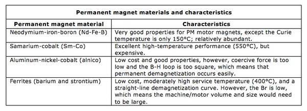
PM motor magnet types
There are few types of permanent magnet materials currently used for electric motors. Each type of metal has its advantages and disadvantages.
Permanent magnet demagnetization
Permanent magnets are hardly permanent and do have limited capabilities. Certain forces can be exerted onto these materials to demagnetize them. In other words, it is possible to remove the magnetic properties of the permanent magnet material. A permanent magnetic substance can become demagnetized if the material is significantly strained, allowed to reach significant temperatures, or is impacted by a large electrical disturbance.
First, straining a permanent magnet is typically done by physical means. A magnetic material can become demagnetized, if not weakened, if it was to experience violent impacts/falls. A ferromagnetic material has inherent magnetic property. However, these magnetic properties can emit in any multitude of directions. One way ferromagnetic materials are magnetized is by applying a strong magnetic field to the material to align its magnetic dipoles. Aligning these dipoles forces the magnetic field of the material into a specific bath. A violent impact can remove the atomic alignment of the material's magnetic domains, which weakens the strength of the intended magnetic field.
Secondly, temperatures also can affect a permanent magnet. Temperatures force the magnetic particles in a permanent magnet to become agitated. The magnetic dipoles have the ability to withstand some amount of thermal agitation. However, long periods of agitation can weaken a magnet's strength, even if stored at room temperature. In addition, all magnetic materials have a threshold known as the "Curie temperature," which is a threshold that defines the temperature at which the thermal agitation causes the material to completely demagnetize. Terms such as coercivity and retentivity are used to define magnetic material strength retention capability.
Finally, large electrical disturbances can cause a permanent magnet to demagnetize. These electrical disturbances can be from the material interacting with a large magnetic field or if a large current is passed through the material. Much in the same way a strong magnetic field or current can be used to align a material's magnetic dipoles, another strong magnetic field or current applied to the field generated by the permanent magnet can result in demagnetization.
Self-sensing versus closed-loop operation
Recent advances in drive technology allow standard ac drives to "self-detect" and track the motor magnet position. A closed-loop system typically uses the z-pulse channel to optimize performance. Through certain routines, the drive knows the exact position of the motor magnet by tracking the A/B channels and correcting for error with the z-channel. Knowing the exact position of the magnet allows for optimum torque production resulting in optimum efficiency.
Servomotors
Servomotors are permanent magnet motors used for motion control applications. Typically, in an interior/internal permanent-magnet motor design, these motors are paired with a specific amplifier as part of a matched set to maximize performance. The amplifier has been fine tuned to the PM motor to reach optimum performance by its manufacturer. The motion amplifier/servo configuration typically uses motor feedback, which also provides a magnetic pole position and speed feedback.